
CNC Mill Conversion - Mechanical
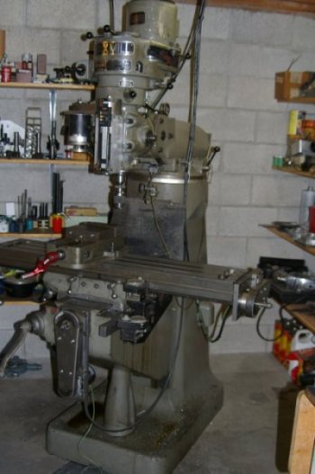
I have converted an older Super Max knee mill to CNC operation. It is a stepper based system using size 34 motors, about 650 oz-in. I changed the lead screws out with a Rockford ball screw conversion kit. This worked very well and saved a great deal of effort. The motors drive the lead screws through 2:1 timing belt reductions.
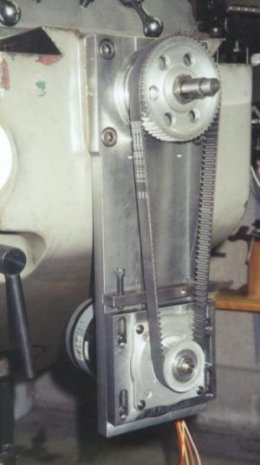
The two figures below show the X and Y axes without their belt covers.
 |
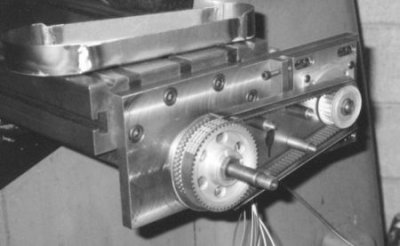 |
The bearing plates were replaced with larger plates to hold the stepper motors. The belt tensioning mechanisms can be seen in these photos. These plates work quite well. Construction was reasonably straight forward. I converted the X and Y axes first then used this 2 axis machine in building the quill Z axis conversion.
The Z axis presented a more difficult design problem. I wanted to do the Z retrofit (as well as the X and Y) without modifying the mill, i.e. use existing mounting points. In the Z I also wanted to maintain the full 6 inches of travel, be able to disconnect the Z axis from the ball screw, and allow access to tilt the milling head. This, as I said, was quite a design task but I was able to meet all these goals.
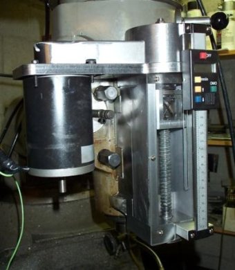
The photos below shows the final results, with and without covers. I put an inexpensive readout on this Z axis. I have readouts (mechanical) on the X and Y axes and find them very useful though they aren't as critical with CNC operation.
 |
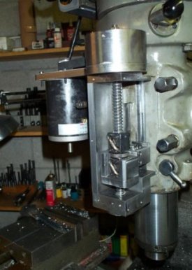 |
A 2:1 timing belt is used between the stepper and the ball screw. The ball screw is supported with a pair of angular contact ball bearings at the bottom, and a floating ball bearing at the top. The cylinder on top puts the upper bearing above the pulley so the ball nut has room to allow the full 6 inches of quill motion. The whole assembly mounts to the holes where the quill stop used to be.
It is hard to see in this picture but the ball nut is mounted to the quill through a dove tail joint. This can be released to disconnect quill motion from the ball screw. The picture below better shows this joint. The ball nut is in the square assembly to the left. The block to the right clamps the dove tail with two socket headed caps. The square section to the far right bolts to the milling machine quill.
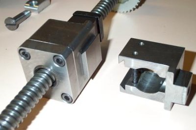
I haven't yet used this dove tail to release the quill. It seems as easy to jog with the CNC controller than bother releasing it. The only time I miss moving the quill by hand is starting taps. I've found a way around this, I just need to build the mechanism. However, the dove tail is needed as I can't install the quill drive without this joint.
I'm very pleased with the mechanical side of this conversion. I still need to install limit switches. Since these aren't necessary for operation the time and cost to implement them causes procrastination.
All in all a very successful project.