
PM1022 Bench Lathe CNC Conversion
Electronics
The stepper motor control is done with a Mesa 7I76 break out board, matched with a 5I25 board inside the control computer. These drive two, X and Z, Gecko G201X stepper drivers. I figured I'd pick up a cheap PC from EBay. However, the 5I25 board is a PCI bus device. Heck, that's new technology so any old computer, particularly a few versions old, would have that. Nope. The PCI bus is gone the way of the S100 and IDE buses. Note: The PCI and PCIe are not compatible. I finally found an old, or reproduction, Intel mini-ITX D425KT mother board. Real old technology but has one PCI port and even a parallel port. I had some trouble getting LinuxCNC installed and running but this, and the one for the PM728, are working fine.
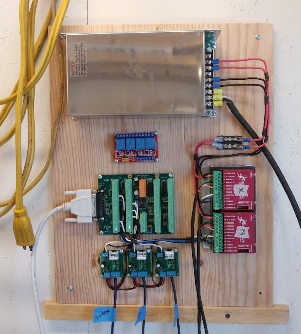
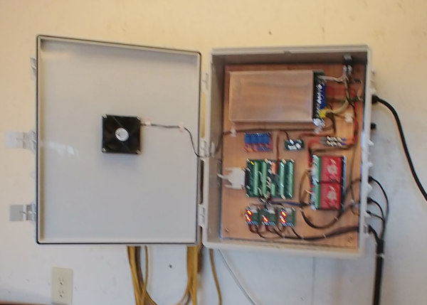
The picture above shows the electronics. The silver box at the top is a 48V/12.5A DC power supply. On the very top is a latching on/off switch for the whole box. The blue box to the left is a board with four relays for coolant etc. Not connected yet but available for expansion. Not yet mounted in this picture is buck converter which converts power supply voltage of 48VDC to the lower Field Power needed by the Mesa 7I25. All the way to the left are fuses. The 7I76 and Gecko Drivers are near the middle. Finally there are three C3 Pulse Index Cards from CNC4PC. These last condition the signals from photo sensors for interface with the 7I76 board. They are used for an encoder described below. Here's the whole thing installed in a box. I put it all, including the backing plywood, into the box. The buck converted has been added here along with a latching on/off switch on the very top. (I appologize for the focus).
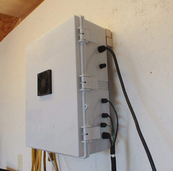
The control box can be mounted on the wall, or on the back of the enclosure. It hangs on the wall for easy access if doing work, but hangs behind the machine to keep it as one package and a to save a little space.

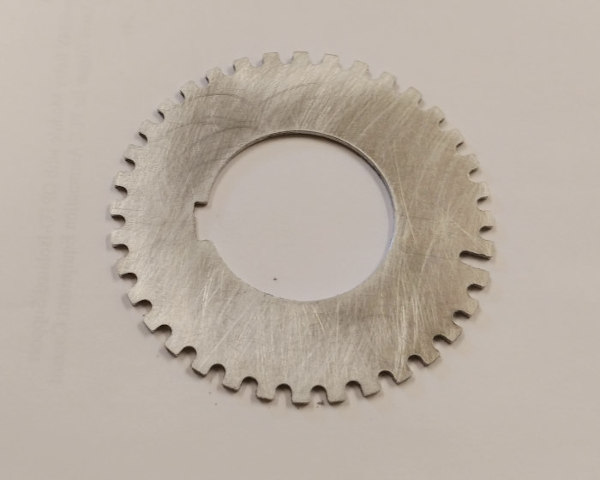
Three photo sensors were used to build up an encoder. An encoder here is used for spindle position feedback. It is needed for CNC threading using LinuxCNC (or any other controller). The encoder disk was cut as below and mounted on the outboard end of the spindle. It has 36 slots with one longer index slot.
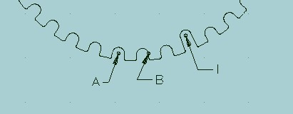
The diagram above shows the position of the sensors. The two outer sensors (A & B) are out of phase by 90 degrees. Counting is done on rising and falling signals so this give 4 pulses per slot, or 144 pulses per revolution. With the sensors offset by 90 degrees the software can sense whether the rotation is forward or reverse. The index pulse in the long slot (I) giving one pulse per revolution. It synchronizes the counting of pulses, i.e. in the zero point for counting.
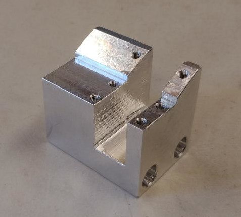
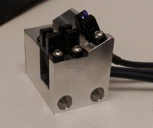
A bracket was built to hold the sensors in position. It's shown as machined and a picture of the bracket with sensors attached follows.
The encoder doesn't give a stable RPM readout from LinuxCNC. I'm not sure why this would be but it is able to thread under CNC control. I may replace it with a real encoder one of these days, but as long as it threads correctly I may not. Don't know yet.