PM1022 Bench Lathe CNC Conversion
X Axis Cross Slide
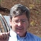
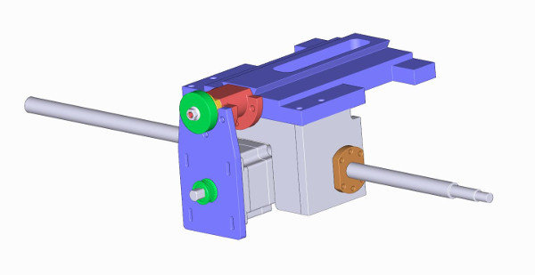
I started with the X axis as it seems to be the trickiest part. Just fitting the ball screw in was a trick in itself. I wanted a double nut but had trouble fitting just a single in. The model below shows the X axis configuration along with the apron. The picture below this shows the actual configuration as built.
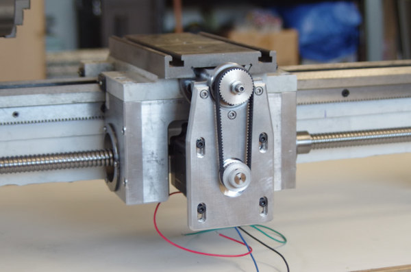
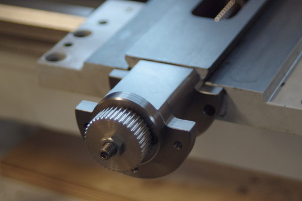
You can see I used a timing belt drive to tuck the motor back into the apron. Space is very tight in the winter shop so every space saving opportunity is taken. This also keeps the motor out of the way when working near the carriage. If the motor stuck outward, the size of the enclosure would have to be considerable larger.
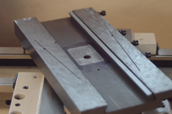
The block at the front holds two angular contact bearings with corresponding spacers. It is cut down so the cross slide moves forward over it. This and cutting the slot larger retained the original travel of the cross slide. Another thing that made it tricky is the slot doesn't quite align with the mounting hole. This was OK with the stock acme screw and nut, but interfered with the new ball screw. The bearing block was built with an offset between its mounting and the bearing center line. Lots of measuring, fitting and two tries at that part.
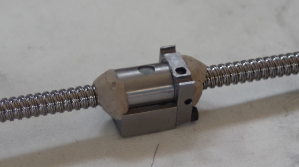
The angular contact bearings, spacers and machined ball screw end are shown here. A tool post grinder was used to machine the end of the ball screw. Once through the surface, in the softer core material, standard tooling could be used for the keyway and threads.
The ball nut housing needed to be machined quite a bit to fit. It is hardened but patience and carbide allowed machining. This picture of the bottom shows the original mounting holes nearly cut off. I blocked the screw with clay so it wouldn't get too contaminated.
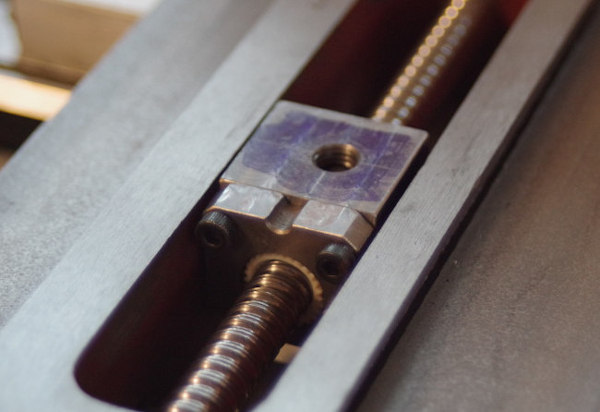
This shows the ball nut installed. You can see how tight the fit is even for this heavily modified ball screw nut. It's not quite centered in the slot but it has clearance through it's motion. I also cut a shallow pocket on the underside of the cross slide casting. It needed just that much more clearance.
This picture shows the completed construction. You can see how the timing belt is configured and the stepper motor tucked into the apron.