
Ziggy - New Electrical Integration
The Explorist motorhome upgrade has the original coach battery removed, and a wiring run (+ & -) from the old battery connections to the new Lynx Distributor. This is essentially what was done. The PDF wiring diagram explains what was done, but the following shows in detail the wires involved.
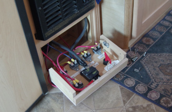
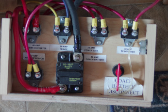
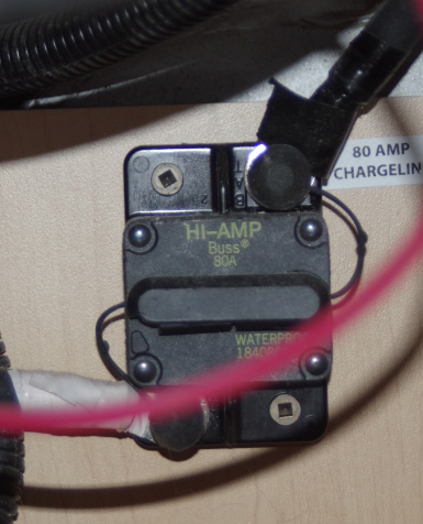
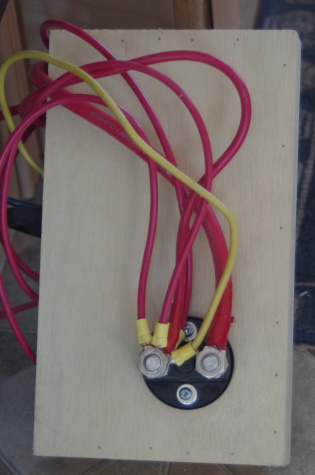
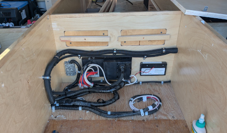
The breaker cabinet is located under the furnace in our PleasureWay. The first picture below shows the "breaker board" with all the higher current 12V breakers in its original configuration. This fits into the Breaker Cabinet. Studying this board goes a long ways in understanding the circuits. Let's consider the original wiring first. The second pic shows the front side of the breaker board. Here the largest breaker seen is the main 80A battery breaker. There are two large black wires (hard to see lower one) connected to the upper terminal. One comes from the positive battery terminal in the battery compartment. The second heavy black wire comes from the vehicle battery/alternator, through a battery issolator and 80A breaker. The third pic shows this second 80A breaker which is mounted on the wall behind the breaker board. Thus the original battery positive terminal is connected, through some protection, to the vehicle battery/alternator for charging. The other side of this breaker, red wire, passes over the top to the back of the breaker board. The back is shown in the fourth pic below. That positive red lead goes into one side of the "red" switch, the original battery disconnect switch. The other side of the "red" switch feeds all the other 12V breakers on the front.
 |
 |
 |
 |
Now let's consider the wiring as modified. The wiring diagram is shown on the main electrical page as a PDF. Visually the new wiring varies little from original, but there are a few important changes. The wire going from the 80A breaker on the breaker board to the hidden alternator breaker has been removed. This severs the connection of the vehicle battery/alternator to the coach battery and 12V circiuts. This is needed as the alternator is not directly compatible with the new lithium system.
On the back of the breaker board a second red lead is attached to the "red" key. This wire is routed to the new positive lithium battery terminal, through the lynx distributor. Thus, if the "red" key is on, the 12V breakers and systems are "hot". The negative lithium battery terminal is grounded, via the lynx distrubtor, to the chassis near the Victron equipment. All the 12V circuits use the chassis as ground, standard automotive practice, so everythng works.
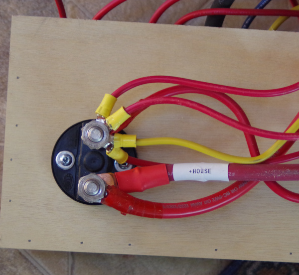
The original positive battery lead is retained for power in the battery compartment. It is the red lead from the "red" switch, looping over the breaker board, through the original 80A battery breaker, and on into the battery compartment.
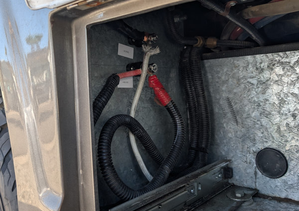
A black negative lead is carried from the lynx distributor ground, to and through the breaker cabinet, and into the battery compartment. That gives two heavy leads, positive and negative, in the battery compartment. Each are connected to isolated terminals. This configuration should avoids any ground loops. The Onan starter power comes from these power leads in the battery compartment. Those heavy leads may be used later for an air compressor mounted in place of the old battery.
The alternator can't be directly connected to the new lithium battery circuit. This is why the circuits were severed above. For charging from the alternator a line needs to come from the vehicle battery/alternator to the Orion DC/DC charger. The Orion takes care of the lithium charging cycle. Rather than run a new line from the vehicle battery I used the existing charge line running to the breaker cabinet. It goes to the alternator charging 80A breaker buried at the back of that cabinet. I simply put a (red) line to this breaker and ran it to the Orion. Rather than run a new ground line I simply tied the negative terminal of the Orion to the Lynx negative bus bar (which is grounded to the chassis). Grounding is then as original, through the chassis. The Orion is connected, through the Lynx distributor, for charging the lithium battery.
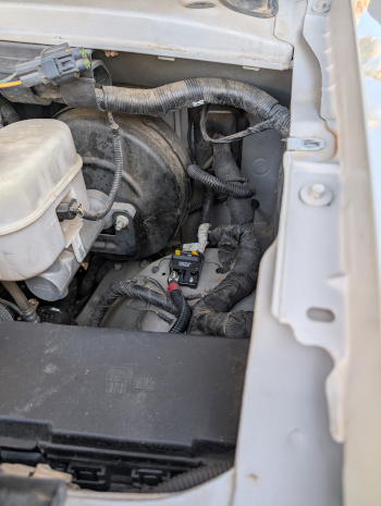
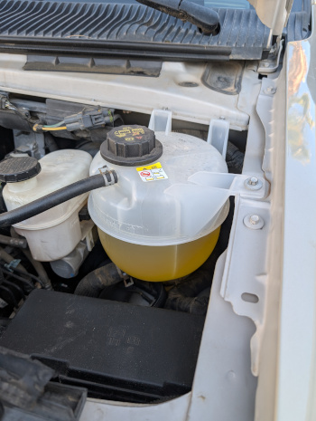
This original alternator charging line came from the Ford fuse box, through a battery issolator, and into the breaker cabinet. In the engine compartment I simply replaced the issolator, under the hood, with a 60A breaker. The tank, when in place, makes it hard to see the breaker.
 |
 |
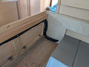
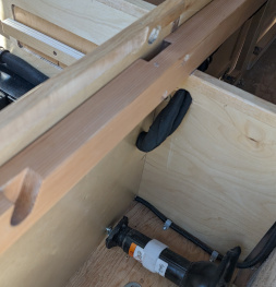
There are then three new wires routed between the breaker cabinet and the Victron equipment. Two leads (red/black), connecting to the lithium battery, are encased together in a fabric loom. The third wire (red), connects the vehicle battery/alternator to the Orion DC/DC charger, is encased in its own woven loom. All are routed through the wall, along the passengers cabinets, into the center "box" (where fuse box is), and to the Victron cabinet. Loom was used to avoid wear.
 |
 |
 |
A couple of notes are in order. The 80A breaker, through which the coach battery was connected, is of little use. If anything it protects the wiring run from breaker cabinet to battery compartment. However, there is a fuse in the Lynx Distributor to protect this whole line. It is 160A though, so this 80A could trip. Likewise, the "red" switch only cuts off power to the coach 12V systems, not a true battery disconnect. It could be taken out of the system with no problems (other than the hole in the panel) as there is a true battery disconnect in the Victron cabinet.
The 80A alternator breaker is really not needed. A 60A breaker was installed at the vehicle battery to protect this line. It will blow before the 80A breaker.
For these it was easier to keep the components than wire around them, and they do no harm.